How to create a transfer function to model a linear time invariant system.
Closed loop transfer function matlab.
Example h getiotransfer t in out openings returns the transfer function calculated with one or more loops open.
Two transfer functions are combined to create a plant model.
In the example above h2 has double the order of h.
Enter the following commands into an m file and run it in the matlab command window.
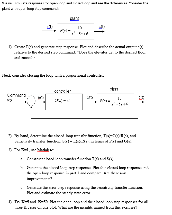
You can add a controller and compute the closed loop transfer function.
The closed loop transfer function of the given system with a pd controller is.
The root locus of an open loop transfer function is a plot of the locations locus of all possible closed loop poles with some parameter often a proportional gain varied between 0 and the figure below shows a unity feedback architecture but the procedure is identical for any open loop transfer function even if some elements of the open loop transfer function are in.
C pid kp 0 kd t feedback c p 1 t 0 0 01 2.
You can read the damping ratio of the closed loop poles from this chart see labels on the radial lines.
The closed loop poles marked by blue x s lie in the left half plane so the feedback loop is stable for this choice of gain k.
To compute the stability margins of this system with the margin command which assumes negative feedback you need to use the negative feedback open loop response.
For example consider the following system where t is the closed loop transfer function from r to y.
This is because the expression g 1 g k is evaluated as a ratio of the two transfer functions g and 1 g k.
A major issue with computing h from the formula is that it inflates the order of the closed loop transfer function.
8 let equal 300 as before and let equal 10.
Here the damping ratio is about 0 7 suggesting a well damped closed loop response as confirmed by.
Run the command by entering it in the matlab command window.
Using the results of section 3 5 the digital control system of figure 3 1 yields the closed loop block diagram of figure 3 14 the block diagram includes a comparator a digital controller with transfer function c z and the adc analog subsystem dac transfer function g zas z the controller and comparator are actually computer programs and replace the computer block in figure 3 1.

